Pixel Multiplication with the vDAQ
There can be situations where multiplying pixel values is desirable. The value of a pixel is the summed values of multiple samples from the digitizer. The amount of samples summed into a single pixel is the “pixel bin” count. In standard configurations, pixel values are averaged by multiplying the summed sample values by the inverse of the pixel bin count:
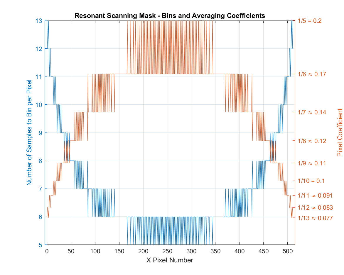
With a resonant scanner, we average pixel values and correct for spatial warping with varying sample bin counts per pixel. See Line Formation for more information. The table of bin counts per pixel for a resonant line is known as the Resonant Scanning Mask.
For example, a 512 x 512 image with an 8kHz resonant scanner at 80MHz sampling rate produces the following resonant mask table to resolve the spatial profile of the scanner:

Sometimes low-valued digitizer samples, which can be common in certain configurations (e.g. photon counting on the vDAQ), can cause the pixel values to go to zero when multiplied by small coefficients. In this situation, the resonant scanning mask can end up over-scaling the summed sample values, reducing them too much.
To correct for this with the vDAQ, one can multiply all pixel values by a constant coefficient.
Setup
Open the Machine Configuration for the vDAQ Imaging System.
Select the Advanced tab.

Click the Enable checkbox next to “FPGA Pixel Multiplier Coefficient.”
Type a desired coefficient for multiplying pixel values.
This will be multiplied in the FPGA backend.
Supported values:
MAXBIN,MINBIN,MEANBIN, and any numeric constant.MAXBIN: multiply by the maximum bin count in the resonant scanning maskMINBIN: multiply by the minimum bin count in the resonant scanning maskMEANBIN: multiply by the average bin count in the resonant scanning maskany numeric constant: multiply by a specified constant, e.g. 500 or 0.1
Note
When linear scanning,
MAXBIN,MINBIN, andMEANBINare equivalent and are equal to the linear pixel bin factor.Click the Apply button to save and apply the settings.
Resonant Profile Constant Coefficient Multiplication Examples

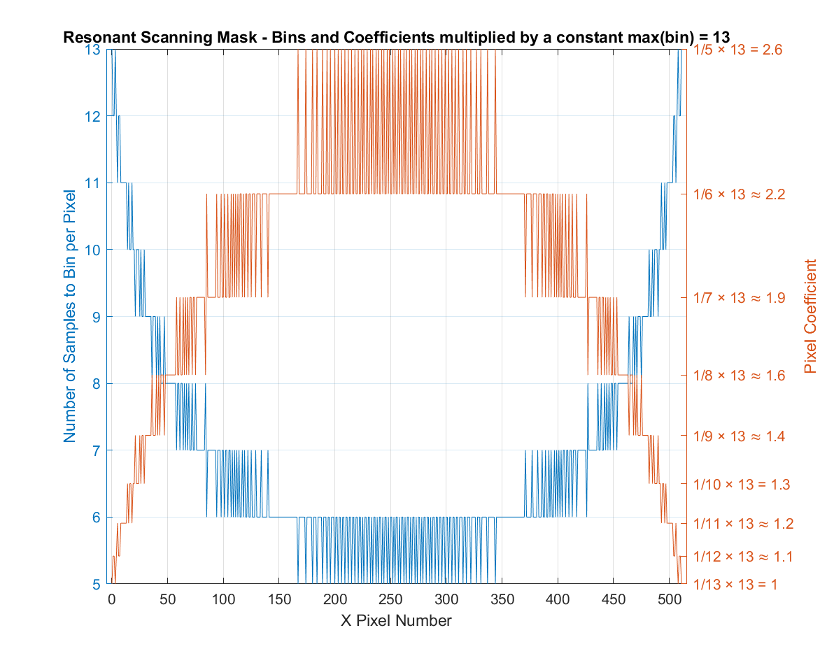
In the earlier example, the max bin count is 13. Using MAXBIN
as the FPGA Pixel Multiplier Coefficient multiplies each mask
coefficient by 13 to produce the above resonant mask table.
In this configuration, no pixels are being divided (i.e. all pixel coefficients are ≥ 1.0). The pixels at the edge of the profile are unchanged, while the pixels in the middle are multiplied-up to adjust for the velocity of the resonant scanner.
This is useful for very low valued pixels, since no pixel division will occur with this coefficient.

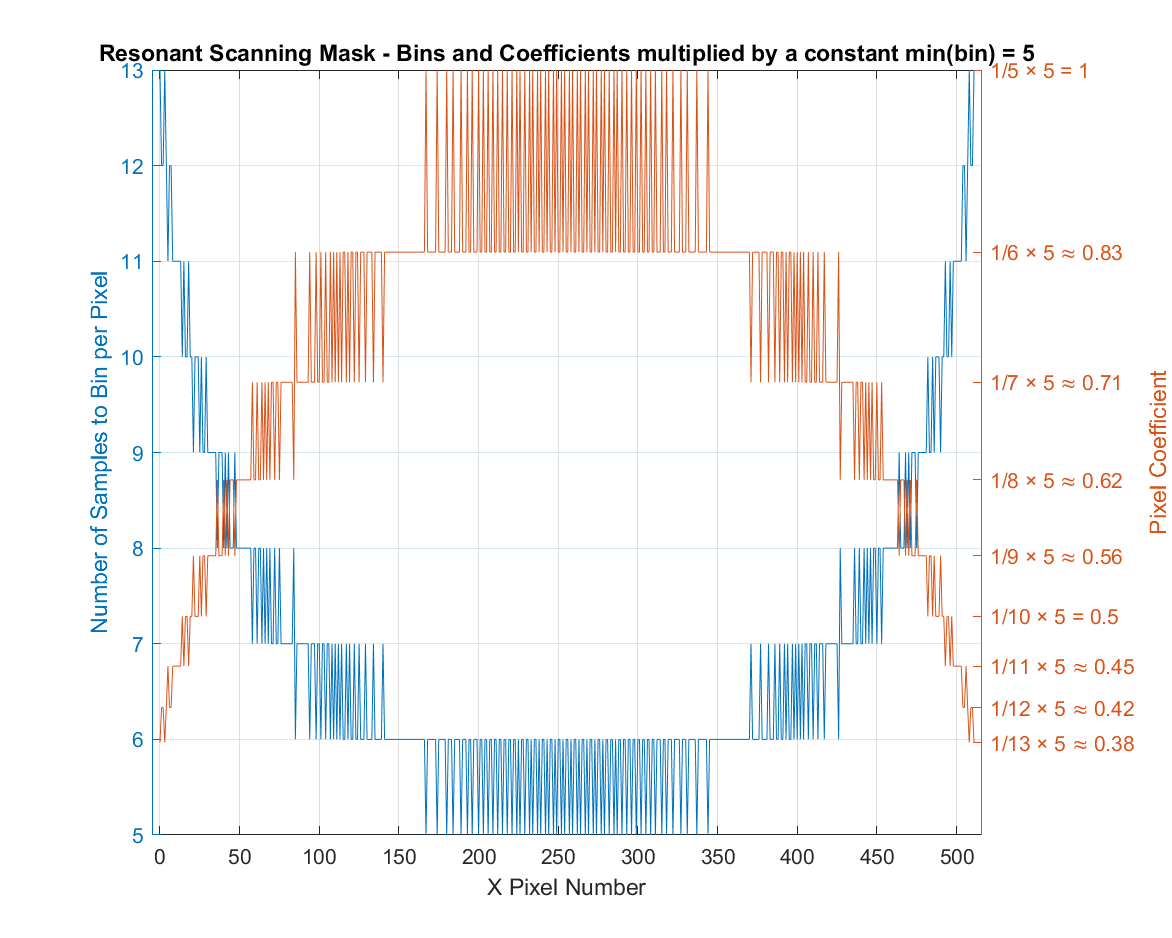
In the same example, the min bin count is 5, using MINBIN
multiplies each coefficient by 5 to produce the above resonant
mask table. This up-multiplies the mask, but to a lesser degree
than using MAXBIN.
In this configuration, pixels in the middle of the profile are not changed, and pixels at the edge of the profile are divided to adjust for the velocity of the resonant mask.
This is useful in cases where MAXBIN oversaturates the middle
pixels by overmultiplying. With MINBIN, the max scaling coefficient
applied to an unaveraged pixel is 1.0 at the middle of the profile,
and the rest of the pixel values are divided
(i.e. have coefficients < 1).

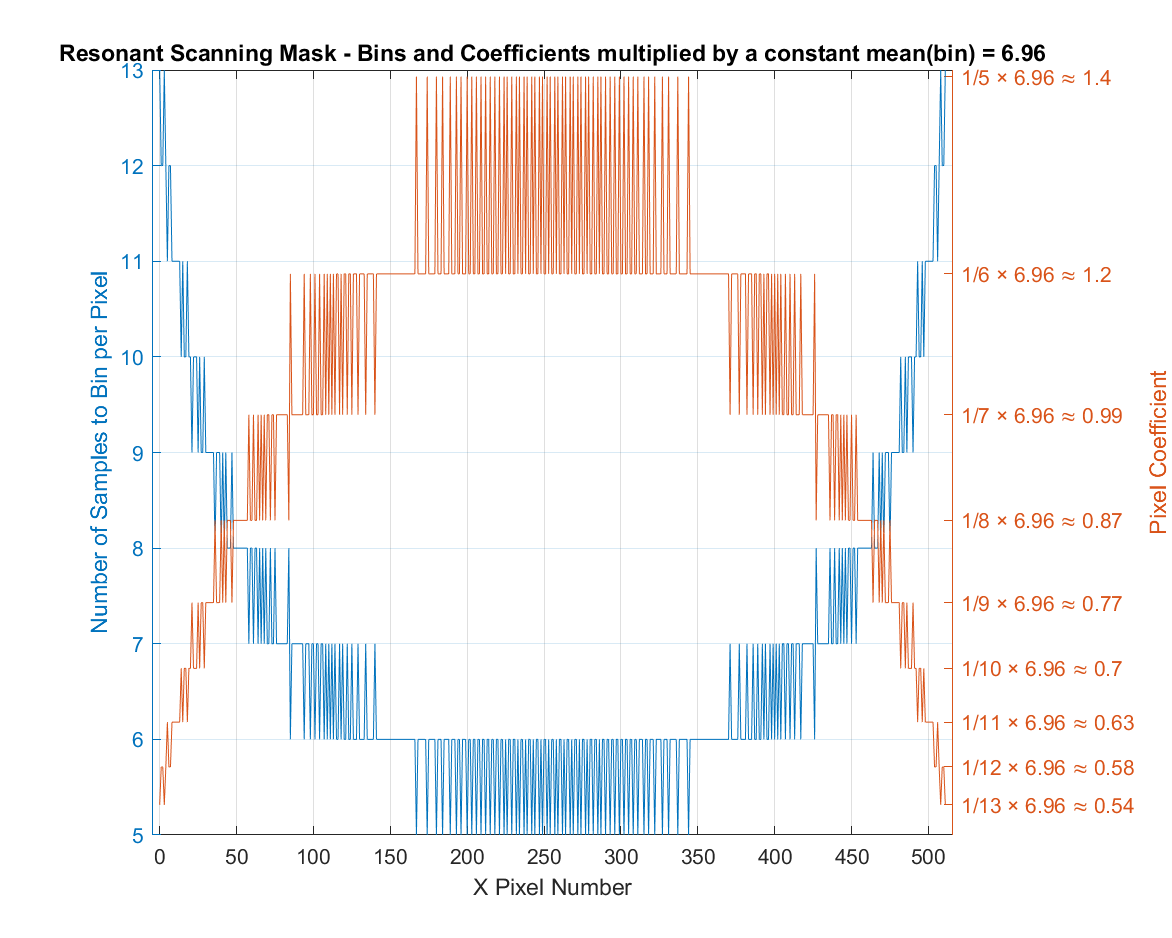
In the example, the average bin count is 6.96. Using MEANBIN
multiplies each coefficient by 6.96 to produce the above resonant
mask table.
MEANBIN is an option that is in between MAXBIN and MINBIN.
In this configuration, some of the pixels will be divided and others
will be multiplied.
With MEANBIN, the pixels closer to the edge (slower velocity)
are divided (i.e. have a coefficient < 1), and the pixels in the
middle are multiplied (i.e. have a coefficient > 1). This provides
a balance for medium valued samples.