Analog FastZ
The Analog FastZ driver is meant to be a generic driver for the control of fast focus devices which are controlled via analog signal.
Hardware Setup
Turn off and disconnected power from the controller. Connect the fast focus piezo device to the controllers driven output port.
Position command and feedback connections are slightly different for different DAQ hardware.
For vDAQ
Connect a BNC cable from a free analog output on the vDAQ breakout box to the Position Command Input on the controller.
Connect a BNC cable from a free analog input on the vDAQ breakout box to the Position Feedback Output on the controller.
For NI DAQ
A fast focus device runs a DAQ mx timed task, and as such, must not be assigned ports on a DAQ that already has another device with its own timed tasks (e.g. beam modulator or galvo scanner). Once such a DAQ is available:
Connect a BNC cable from a free analog output on the breakout box belonging to that DAQ to the Position Command Input on the controller.
Connect a BNC cable from a free analog input on the breakout box belonging to that DAQ to the Position Feedback Output on the controller.
Once these connections are made, the power cable can be plugged in and the unit turned on.
ScanImage® Configuration
In ScanImage, open the Resource configuration window from the startup dialog or from the Main Controls window under File>Configuration.
From the Resource Configuration window, click the “+” button. Select Fast Focus from the sidebar, and select Analog FastZ. Give it a name and continue.
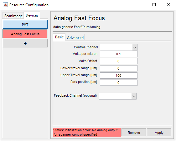
A window like shown to the below should appear. Below is a description of each of the configuration parameters
Basic Page |
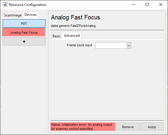
Advanced Page |
|
|
Basic Configuration
Control Channel |
The Analog Output port which was connected to the Position Command Input of the controller. |
Volts per micron |
Assuming a linear control relationship, this is increment in command voltage required to increment the focus depth by 1 micron. |
Volts Offset |
The voltage at which ScanImage® coordinate system will define the depth as being 0 um. |
Lower travel range [um] |
The lowest (most negative) extent of the device’s travel. |
Upper travel range [um] |
This is highest (most positive) extent of the device’s travel. |
Park position [um] |
The position when not acquiring, i.e. when not acquiring or pointing. |
Feedback Channel (optional) |
The Analog Input port which was connected to the Position Feedback Output of the controller. |
Advanced Configuration
Frame clock input |
This is the Digital Input port which will receive the frame clock signal |
Click Apply to apply the configuration to this device. It can now be used as a beam modulator for a ScanImage® scanner object.