ROI Integration Output Channels
Integration outputs can be used to drive software, analog, or digital outputs. A user-defined function must be provided in order to process the data from a list of selected integrated regions.
Channel Configuration
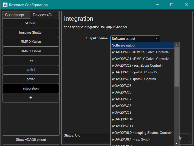
To configure output channels, open the Resource Configuration Editor and locate the Integration ROI Output Channel under section Online Analysis. Name the device such that it indicates the type of output it will generate.

Each output channel can be of one of the following types:
Daq Name |
Channel ID |
Description |
|
Software output |
None |
None |
Does not generate an output, just calls the user defined output function |
Analog Output |
<DAQ Name> |
AOx |
Outputs an analog signal on the specified analog output |
Digital Output |
<DAQ Name> |
Dx.x (vDAQ) PFIx (NI hardware) |
Outputs a digital signal on the specified PFI channel |
Configuration Editor
Configuration of three output channels: Software, Analog Output, and Digital Output; The Channel Name can be chosen arbitrarily.
Note
A ‘Software output’ channel does not require any data acquisitIon hardware. It can be used with the ScanImage API to control the Acquisition, similar to a User Function.
Channel Output Configuration
The output channel ‘Analog Output 1’ is configured to output the average of Cell2 and Cell 3.
Output Configuration
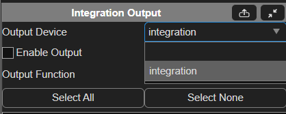
Each output channel can be configured to process the value of multiple integration ROIs. In the Integration Controls, select the ROIs to be passed to the output function.
The output function needs to accept the following inputs:
Input Name |
Description |
|---|---|
vals |
1xN array of integration values of the selected ROIs |
varargin |
advanced parameters |
The output function needs to generate the follwing outputs:
Function output |
Description |
|
Software Channel |
Empty array [] |
Any output by the function is ignored |
Analog Channel |
Numeric scalar within range -10..10 |
Voltage level to drive the analog output |
Digital Channel |
Logical scalar |
Logic level to drive the digital output |
The physical channels are only updated when the output value changes (i.e. if the function generates the same output multiple times, the physical channel is only update once).
Tip
Updating the physical channel is a blocking call in MATLAB. MATLAB execution needs to wait until after the update is completed. To improve performance and reduce latency, PCI(e)/PXI(e) are preferable to USB DAQ devices.
Note
Since ROI Integration and output calculation is done in Matlab, an inevitable time delay will exist between frame acquisition and channel output, even from a physical DAQ board.
User-defined output function
Instead of the default anonymous function, ScanImage® can call a function defined in a .m file on the path. As an example, one can replace the anonymous function call as follows:
Output function call
@(varargin)myOutputFunction(varargin{:})
This user-defined output function can be used to perform a variety of tasks. The following example averages all passed integration values.
Example output function
 1function outputVal = myOutputFunction(vals,varargin)
 2  persistent hLine
 3  persistent history
 4  persistent historyPointer
 5  historyLength = 100;
 6
 7  if isempty(hLine) || ~isvalid(hLine)
 8    hFig = figure();
 9    hAx = axes('Parent',hFig,'XLim',[1,historyLength]);
10    hLine = line('Parent',hAx,'XData',NaN,'YData',NaN,'Color','b');
11  end
12
13  if isempty(history) || length(history) ~= historyLength
14    history = nan(1,historyLength);
15  end
16
17  if isempty(historyPointer) || historyPointer > historyLength
18    historyPointer = 1;
19  end
20
21  outputVal = mean(vals); % calculate the output value by averaging all input values
22  history(historyPointer) = outputVal;
23  historyPointer = historyPointer + 1;
24  if historyPointer > historyLength
25    historyPointer = 1;
26  end
27
28  history(historyPointer) = NaN;
29
30  hLine.XData = 1:historyLength;
31  hLine.YData = history;
32end
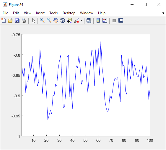
Plot generated by myOutputFunction