Scanner to Scanner Alignment
ScanImage® Premium enables alignment of the scanfields of separate scanners or cameras by applying an affine transformation.
Motivation
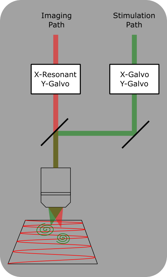
When using a dual scan path microscope for photostimulation, it is often desirable to image and identify cells for stimulation with one scan path, then stimulate the cells using the other scan path. For this targeting to be accurate, alignment between the scanners is critical.
Note
When using the photostimulation with a single scan path microscope, alignment is not necessary. If you are using a resonant-galvo-galvo scanhead however, it is important to have accurate settings for scan mirror angular ranges if you intend to use images collected in resonant mode to identify ROIs to stimulate. Details on how to do this can be found in the scanner configuration pages
Tutorial
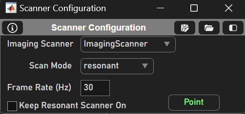
Before aligning the scanners, we must immutably choose one scanner to be the reference scanner. This should be the imaging path of the microscope. Select this scanner from the configuration menu.
Note
Each scanner object hSI.hScan_[User given scanner name] has a scannerToRefTransform property representing an affine transformation to align it to the reference space. The reference scanner’s scannerToRefTransform should be a 3x3 identity matrix.
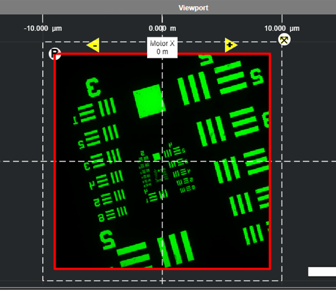
FOCUS on a sample and acquire an image with sufficient structure and contrast so that
the features can be matched from images acquired from each scanner. The scanner’s Zoom factor
can be altered, however it must remain the same for both scanners used in the alignment.
ABORT when satisfied with the image.
Then, pin the current image to the Viewport by right-clicking and selecting ‘RoiDisplays’ > ‘Pin All’ or by pinning the current slice. Change the image color to green by hovering the mouse over the channel and pressing ‘G’.
Warning
Do not move the stage between these steps.
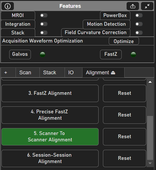
Switch to the other scanner and begin a FOCUS. Open the Alignment Tab by
clicking the plus in the Features GUI and selecting ‘Alignment’. Then, select
the Scanner To Scanner Alignment button. This will open the
ScannerToRefAlignmentTool in the current Viewport.
Also, change the new image color to red. This will make distinguishing the images easier.
Tip
Change the transparency of an image by clicking and dragging the triangle for a channel in the Histograms GUI. This makes aligning image features much easier.
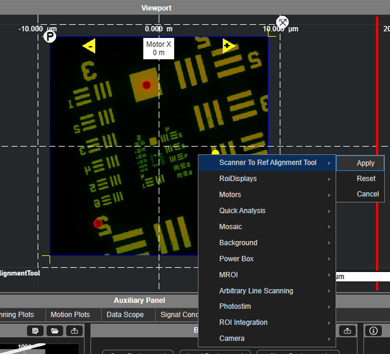
Now, define the scanner to reference affine matrix of the secondary scanner by overlapping characteristic features from the red image onto the green image.
Right click over a characteristic spot in the image to Add a fixed point at that location.
Good contenders for characteristic spots are:
At a corner in an outline
At the centroid of a fluorescent bead that is smaller than the desired spatial resolution.
Then drag the fixed point to the corresponding characteristic spot in the green reference image. Because it is a fixed point, it will remain at that location relative to the reference image while adding and dragging other fixed points.
Dragging the only fixed point will change the X,Y offset of the image without altering XY scale, rotation, or shear.
Dragging one of two fixed points will change the X,Y offset and scale without altering the rotation or shear.
Dragging one of three fixed points will set the all of the X,Y offset and shear as well as rotation and shear.
Tip
Reference points can be deleted by selecting the point and pressing Delete
It is counterproductive to define more than 3 points as only the above affine tranformations can be applied.
Once three fixed points have been defined, the transformation can be saved by opening the Context
Menu and selecting Apply under the Scanner To Ref Alignment Tool.
Camera Alignment
This same process can be applied between the reference scanner and a camera.
The reference image should once again be acquired from a reference scanner. Then select
the camera from the ALIGNMENT SOURCE dropdown. Start acquiring from the camera from the CAMERA
window and it should populate the red image in the Optical Alignment window.
The camera alignment allows images taken from the camera to be used as context images in the ROI Group Editor.