Imaging Systems
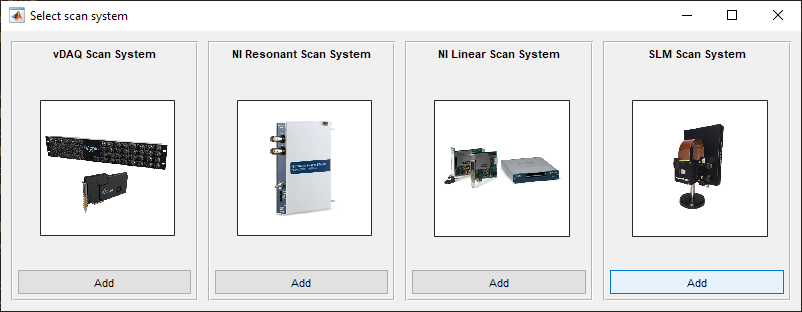
There are four imaging (scan) systems currently supported in ScanImage: the vDAQ scan system, NI resonant scan system, NI linear scan system, and the SLM scan system. An imaging system can be defined as a collection of previously configured devices whose optical, hardware, and software configuration allow them to be used synchronously for the purpose of imaging.
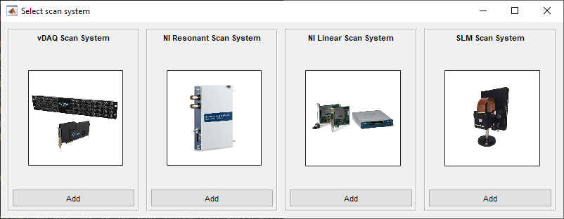
vDAQ Scan System |
This is either a Resonant Galvo Galvo (RGG), Resonant Galvo (RG), or Galvo Galvo (GG) Scan System configured with the vDAQ. |
NI Resonant Scan System |
This is an Resonant Galvo Galvo or Resonant Galvo scan system configured with NI DAQs |
NI Linear Scan System |
This is a Galvo Galvo system configured with NI DAQs |
SLM Scan System |
This is a SLM imaging system configured with either vDAQ or NI DAQs |
Scanner Configurations will henceforth be denoted by their acronyms - RGG, RG, and GG.
Note
See the Scanner Configurations for a description and visual depiction of each scanning configuration’s technique for scanning Multiple Regions of Interest
A scanner system can only be added before launch of ScanImage.
If already launched, exit ScanImage®
and select Modify from the the launcher window.
vDAQ Scan System
This is either an RGG, RG, or GG Scan System configured with the vDAQ.
Once devices are configured, they can be incorporated into the scan system via navigating to the ScanImage tab and selecting the add +Add Imaging System+ button. Select the Add button under the vDAQ Scan System column. Add a name and continue.
This will take you to the vDAQ Scan System configuration page, shown below.
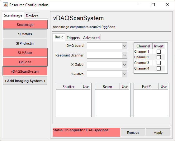
DAQ board |
Select the vDAQ board for acquisition / device control. |
Resonant Scanner |
Select the previously configured Resonant Scanner to be associated with this system |
X-Galvo (optional) |
Select the previously configured Galvo Scanner to be associated with this system’s (fast axis) X-Galvo |
Y-Galvo |
Select the previously configured Galvo Scanner to be associated with this system’s (slow axis) Y-Galvo |
Shutter |
Select the previously configured Shutter(s) to be associated with this system Note: selected shutters will automatically open when an acquisition is started |
Beam |
Select the previously configured Beam Modulator device(s) to be associated with this system Note: selected modulators will automatically be activated when an acquisition is started |
FastZ |
Select the previously configured Fast Focus device to be associated with this system Note: the selected FastZ device will be used for fast z-stacks. |
Channel Invert |
Select the Invert checkbox if the input signal for that Channel is inverted (e.g. more negative for increased light signal). |
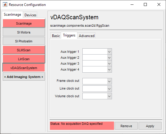
Aux trigger 1 |
Select a DAQ/Port to associate with Aux Trigger 1 |
Aux trigger 2 |
Select a DAQ/Port to associate with Aux Trigger 2 |
Aux trigger 3 |
Select a DAQ/Port to associate with Aux Trigger 3 |
Aux trigger 4 |
Select a DAQ/Port to associate with Aux Trigger 4 |
Frame clock out |
Select a port for outputting the frame clock The frame clock signals the end of a frame |
Line clock out |
Select a port for outputting the line clock The line clock signals the end of a line |
Volume clock out |
Select a port for outputting the volume clock The volume clock signals the end of a stack. |
vDAQ imaging systems
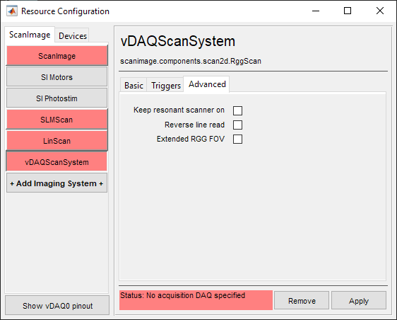
Keep resonant scanner on |
Enabling will keep the resonant scanner on once the imaging system is selected from the Configuration Controls window Tip After enabling a resonant mirror motor, it slowly warms up. This can result in a slow drift of the resonant frequency over time. Keeping the resonant scanner on allows the motor to reach a thermal equilibrium, which achieves a more stable frequency. |
Reverse line read |
Flip the image horizontally |
Extended RGG FOV |
Enables the Resonant mirror and X-Galvo to use their full range of motion for an extended FOV |
NI Resonant Scan System
This is either an RGG or RG Scan System configured with NI DAQs.
Once devices are configured, they can be incorporated into the scan system via navigating to the ScanImage tab and selecting the add +Add Imaging System+ button. Select the Add button under the NI Resonant Scan System column. Add a name and continue.
This will take you to the NI Resonant Scan System configuration page, shown below.
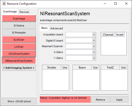
Acquisition board |
The FPGA/Digitizer combination that will be used for Acquiring fluorescence from the PMTs |
Digital I/O board |
Select the Auxiliary DAQ board where triggers or other digital signals should be configured |
Resonant Scanner |
Select the previously configured Resonant Scanner to be associated with this system |
X-Galvo |
Select the previously configured Galvo Scanner to be associated with this system’s (fast axis) X-Galvo |
Y-Galvo |
Select the previously configured Galvo Scanner to be associated with this system’s (slow axis) Y-Galvo * - Linear scanner (optional) |
Shutter |
Select the previously configured Shutter to be associated with this system |
Beam |
Select the previously configured Beam Modulator device to be associated with this system |
FastZ |
Select the previously configured Fast Focus device to be associated with this system |
Channel Invert |
Select the Invert checkbox if the input signal for that Channel is inverted (e.g. more negative for increased light signal). |
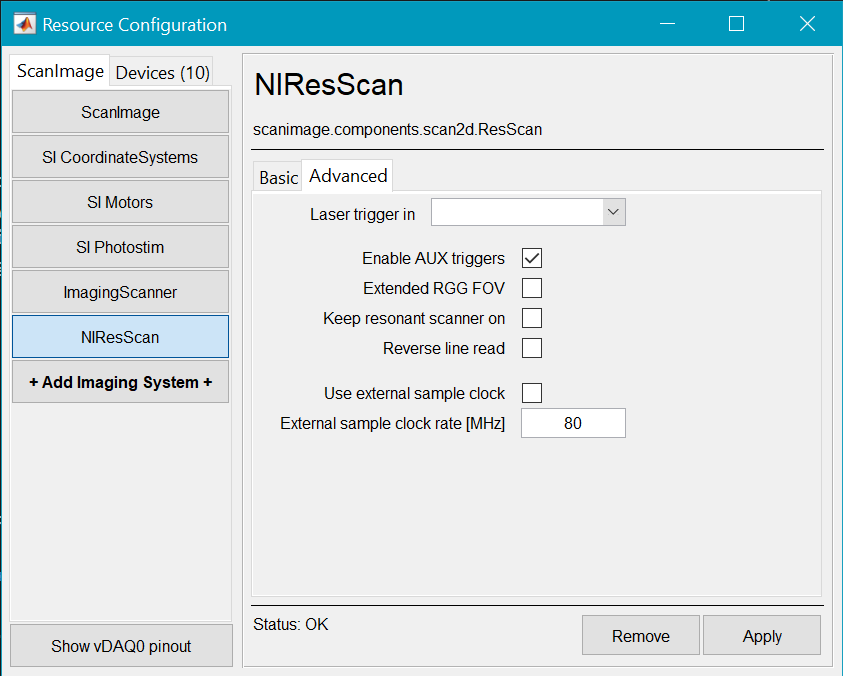
Laser Trigger In |
Select the DI port where the laser trigger signal is connected |
Enable AUX triggers |
Check to enable AUX triggers that are enabled in the Machine Data File |
Extended RGG FOV |
Enables the Resonant mirror and X-Galvo to use their full range of motion for an extended FOV |
Keep resonant scanner on |
Enabling will keep the resonant scanner on once the imaging system is selected from the Configuration Controls window Tip Keeping the resonant scanner on will allow it to achieve a steady state of operation. This prevents variation in the command voltage to mirror amplitude calibration, which is beneficial to experiments where imaging occurs over a long duration |
Reverse line read |
Flip the image horizontally |
Use External Clock |
Whether or not to use an external clock to synchronize to for PMT signal sampling. |
External sample clock rate [MHz] |
The rate of the external clock that sampling should be synchronized to. |
NI Linear Scan System
This is a GG Scan System configured with NI DAQs.
Once devices are configured, they can be incorporated into the scan system via navigating to the ScanImage tab and selecting the add +Add Imaging System+ button. Select the Add button under the NI Resonant Scan System column. Add a name and continue.
This will take you to the NI Resonant Scan System configuration page, shown below.
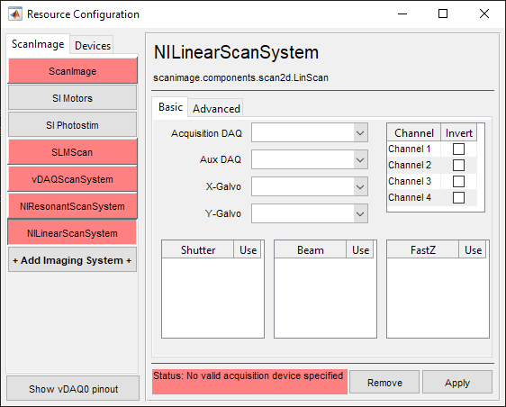
Acquisition board |
The X-Series or FPGA/Digitizer combination that will be used for Acquiring fluorescence from the PMTs. Note Legacy S-Series ni boards PCI-6110 and PCI-6115 are also supported for linear scanning |
Digital I/O board |
Select the Auxiliary DAQ board where triggers or other digital signals should be configured |
Resonant Scanner |
Select the previously configured Resonant Scanner to be associated with this system |
X-Galvo |
Select the previously configured Galvo Scanner to be associated with this system’s (fast axis) X-Galvo |
Y-Galvo |
Select the previously configured Galvo Scanner to be associated with this system’s (slow axis) Y-Galvo * - Linear scanner (optional) |
Shutter |
Select the previously configured Shutter to be associated with this system |
Beam |
Select the previously configured Beam Modulator device to be associated with this system |
FastZ |
Select the previously configured Fast Focus device to be associated with this system |
Channel Invert |
Select the Invert checkbox if the input signal for that Channel is inverted (e.g. more negative for increased light signal). |
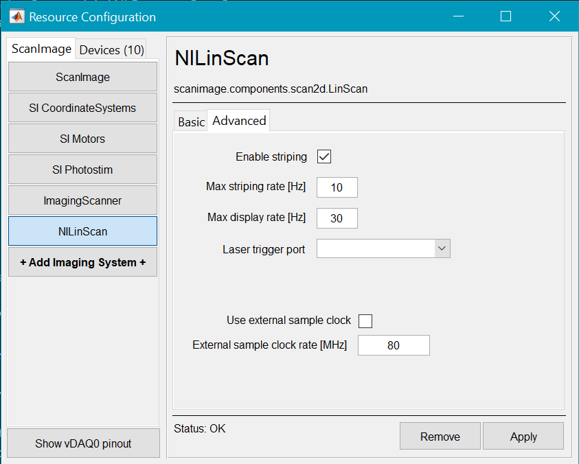
Enable Striping |
Place a check in the box to enable a striping display |
Max striping rate [Hz] |
The maximum rate at which the stripes are acquired. The higher this is, the thinner the stripes being updated. |
Max display rate |
The maximum frame rate for displaying on the monitor (regardless of whether striping is enabled) |
Laser Trigger In |
Select the DI port where the laser trigger signal is connected |
Use an external sample clock |
Whether or not to use an external clock to synchronize acquisition sampling to. |
External sample clock rate [MHz] |
The frequency of the externally provided clock to synchronize acquisition sampling to. |
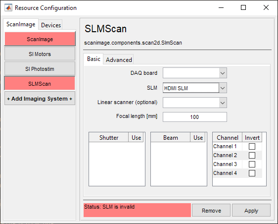
SLM Scan System
This is a Scan System utilizing an SLM to control the illumination of ROIs.
Once finished configuring an SLM device, The SLM can be incorporated into an imaging system via the ScanImage tab and selecting the add +Add Imaging System+ button. For a system with an SLM, select the Add button under the SLM Scan System column. Add a name and continue.
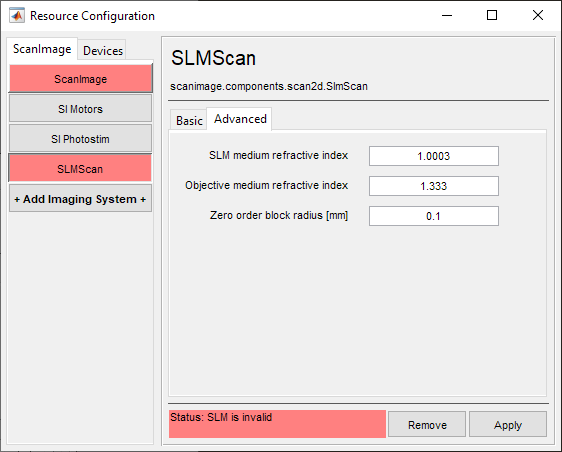
This will take you to the SLM Scan System configuration page, shown below.
|
|
DAQ board |
Select the Auxiliary DAQ board where triggers or other signals should be configured |
SLM medium refractive index |
The refractive index of the medium before the SLM array |
SLM |
Select the SLM device that was configured from the Devices tab |
Objective medium refractive index |
Refractive index of the medium within the objective lens |
Linear scanner (optional) |
Select a previously configured Linear Scan System to be used with the SLM. Note this assumes the Linear Scan System is downstream of the SLM in the beam path. |
Zero order block radius [mm] |
The radius of the opaque medium used to block the zero order center of the focal plane. |
Focal length [mm] |
Enter the intended focal length to operate this SLM in your system |
||
Shutter |
Select the shutter in the SLM beam path |
||
Beam |
Select the Beam Modulator to be used with the SLM |
||
Channel |
Select the Invert checkbox if the input signal for that Channel is inverted (e.g. more negative for increased light signal). |