Stage Scanning
Stage scanning is a technique for scanning a sample by moving the stage perpendicularly to the resonant scanner axis at a constant velocity. This is useful for scanning large areas, or for scanning samples that are too large to fit in the field of view of the microscope. It was particularly developed for use with the tile scanning feature, which allows the user to scan a large area by stitching together multiple strips of stage scanned images.
Tile scans acquired with stage scanning can be used for a preview of a large area, and then smaller areas of interest can be easily revisited with a resonant-galvo scanner, for functional or higher resolution imaging.
Configuration
Currently, this feature is only available for Zaber stage controllers that
have an X and Y axes connected,
Support streamed movement, and
Have digital inputs on the stage controller for receiving the frame trigger signal.
Note
This feature is only available on vDAQ based systems.
Mechanical Considerations
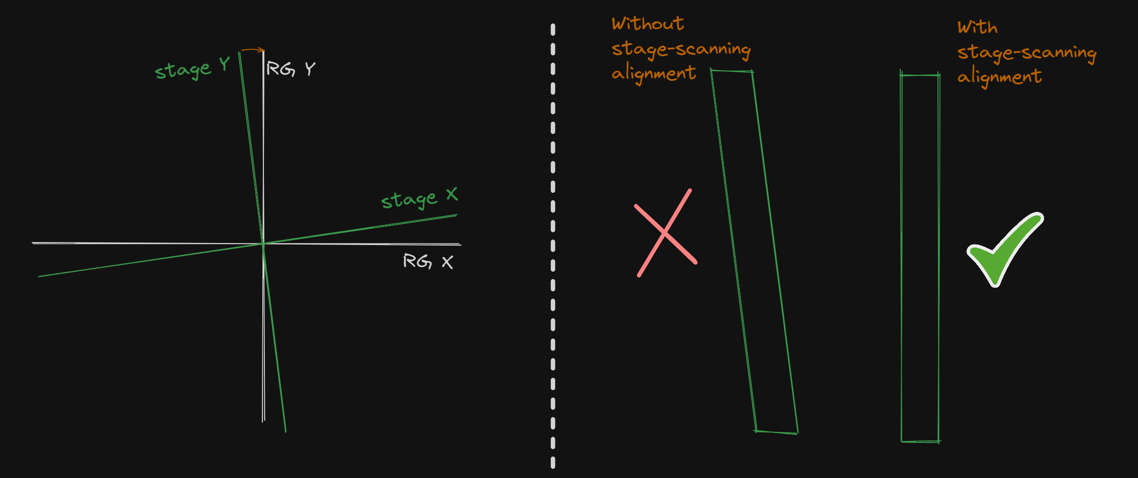
In order to scan perpendicularly to the resonant scanner axis, the stage must have both an X and Y axis. This is because there can be a slight angle between the stage axes and the resonant scanner axis. This angle can be measured using the Stage Scanner Alignment feature and is used to calculate the XY motion required to scan perpendicularly to the resonant scanner axis.
If applicable, it is also advised that the Y-axis stage (the one most perpendicular to the resonant axis) be loaded the least. This can help allow the Y-axis stage to move with higher velocity for faster scans.
Electrical Considerations
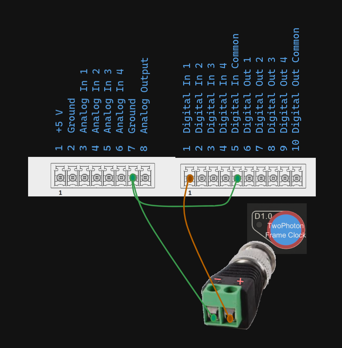
The frame trigger signal is used to trigger the stage to start scanning the next frame. This signal will be output from the digital output BNCs on the vDAQ breakout boxes and needs to be connected to the digital input of the stage controller. For this, a BNC to terminal converter is a practical solution.
The connection can be made as depticted in the following figure for the X-MCC3 stage controller as an example. This may vary depending on the stage controller used. In the case of the MCC-3, the digital pins must be pulled low through the Digital In Common terminal.
Description of Connections: 1) vDAQ Frame clock signal to Controller Digital In 1 2) vDAQ Ground to Controller Ground 3) Controller Ground to Digital In Common
Software Considerations
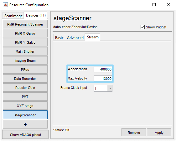
After configuring the Zaber stage controller as a device, a Stream tab will appear.
The velocity and acceleration parameters can be revisited later when tuning the stage for best scanning performance.
To get started, the frame triggering must be configured.
To configure the frame trigger to be output from a digital output, configure the frame clock output from the imaging system configuration page on the triggers tab.
To configure the digital input that should receive the frame trigger, configure it from the stream tab by its number.
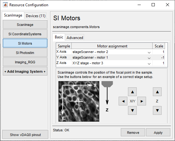
Then, assign the axes of this stage scanning controller to the x and y axes of the SI Motors component through its configuration page.. If this was configured after launching ScanImage, then ScanImage will need to be restarted in order to see the stage scanning option from the Configuration Window’s imaging scanner dropdown menu.
Before doing any stage scanning, you will need to do a Stage-Scanner alignment using the resonant-galvo scanner. In addition to measuring the angle between the stage axes and the resonant scanner axis, this will also measure width of the FOV in microns so that the size and aspect ratio of the scannable area with the stage scanner can be accurately estimated
After this, you might set your sample coordinate system in one of two suggested ways:
Leave the zero position of the sample coordinate system at the zero of the raw motor coordinate system.
Put the zero position in the middle of the stage axes’ range
This is a matter of user preference, but the user should be cognizant of where the stage is relative to the range of the stages to avoid “out-of-bounds” issues when acquisition planning.
Use
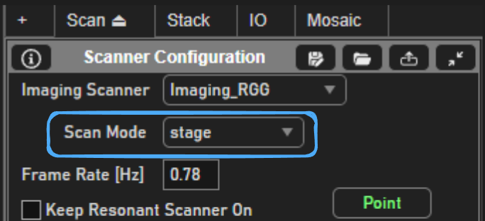
In order to use the stage scanning feature, select the stage scanning option from the imaging scanner dropdown menu in the Configuration Window.
Performance
With stage scanning, the number of lines per frame determines the speed of the stage movement during acquisition and the frame flyback time determines the speed during flyback. The minimum frame flyback time will be determined by the user set maximum velocity and acceleration of the stage during streamed movement.
The default values for the velocity and acceleration may not be optimal for your stage. For example, the default acceleration may be too high in which case the stage may remain in place when it should be in motion. If this is the case, the acceleration should be lowered. If the acceleration is too low, then there will be more lines at the beginning and end of each frame that are distorted than would be optimal. The only way to find an optimal acceleration is via trial and error with acquisitions on a test sample. The same goes for the velocity.
If the number of lines configured for an acquisition is low enough that the required speed is greater than the user set maximum speed, then ScanImage will throw an error when trying to acquire. In this case, the user should increase the number of lines per frame.
Combination with other features
Stage Scanning can be used with such features as:
Note
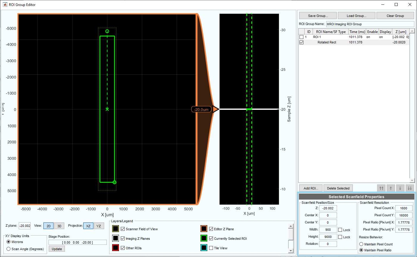
scanning of multiple ROIs with the MROI feature is not supported, however defining a single ROI to scan with the MROI enabled is how strip scanning is accomplished.
and more.
Planning where to scan
By default, without using the MROI scanning feature, the stage will scan only a square of a side length equal to the width of the acquired portion of the resonant scanner amplitude. To scan a strip, the MROI scanning feature must be used to define a single strip-shaped ROI. The acquisition will always be planned with the zero position of the reference space (the space that the ROI is defined in in the ROI Group Editor) at the current stage position. For example, if the stage is at sample position [200 200] microns and the user defines an ROI with a Center X and Center Y of [0 -200] microns in sample relative space, then the stage will scan over an area that is centered on sample position [200 0].
Note
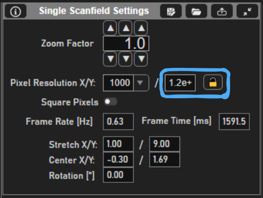
It’s easy to force the pixel aspect ratio to be 1:1 by ensuring the ratio of width to height of the ROI is equal to the ratio of pixel count X and pixel count Y.
At the end of acquisition, the stage axes will be returned to the pre-acquisition position so that subsequent acquisitions will acquire from the same parts of the sample.