Thorlabs BCM-PA
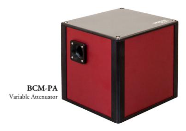
Thorlabs BCM-PA is a device that can be used to modulate beam power within ScanImage. It contains a rotation stage inside it holding a half wave plate and a polarizing beam splitter and beam dump to divert excess laser power.
It also has a shutter. This can be controlled via our digital shutter device or manually via the joystick by pressing down on the knob.
Device Setup
Connect the controller to the PC via supplied USB cable. Optionally connect the joystick as well.
Note
ScanImage does not intercept messages between the joystick and the BCM-PA, and so the joystick can defy limits set on beam power that were configured within ScanImage.
Connect the controller to power via the included power adapter.
Use an SMA male to BNC male cable
to make a connection from a digital output port to the SHUTTER input.
Note
The BCM-PA will home upon startup to its zero position and close the shutter. This zero position may or may not be the minimum power position, so refrain from opening the shutter until ScanImage has been launched. Initialization of the BCM-PA device in ScanImage will set it to the configured minimum power position.
Software Setup
Execute scanimage in the command window to access the splash screen and click Modify
to open the configuration window. Under the Devices, select the + button.
Select the category ‘Thorlabs’, and select BCM-PA. This is simply for
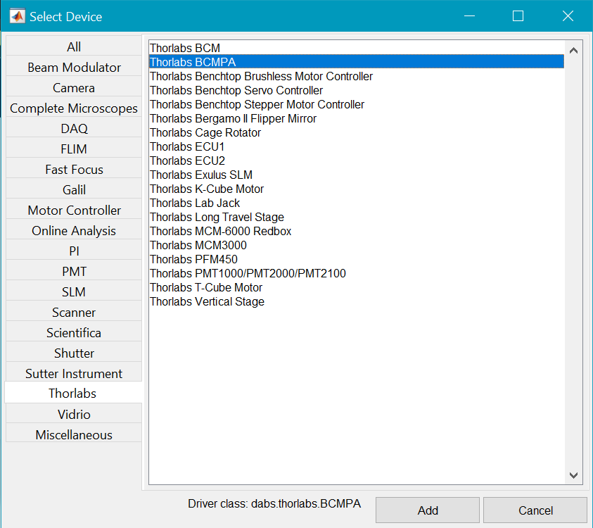
This will add two configuration pages related to the BCM-PA device. The first is for the motorized half-wave plate for beam power modulation, and the second is for the upstream shutter.
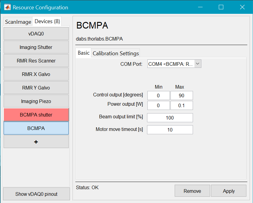
Below are the descriptions of the options available from this page:
|
|
COM Port |
Select the COM Port belonging to the BCM-PA from the dropdown. If you are unsure which COM port belongs to the BCM-PA, you can open the windows device manager and look under COM ports. If the Thorlabs BCM-PA software has been installed, the COM Port will be labeled BCM-PA. 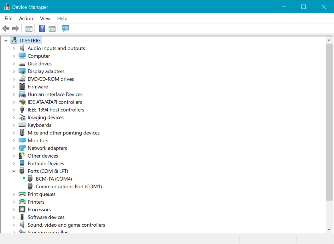
If not, then you can simply disconnect and reconnect the USB cable for the BCM-PA from the computer while watching the device manager to see which COM port disappears and reappears. |
Output Range |
This is the lower and upper bounds of travel of the rotational stage in degrees. Use values between 0 and 360. One could just assign a large enough angle range in degrees (90) and the calibration with photodiode will find an appropriate, continuous sub-range of angles to find the minimum and maximum power. Note Rotating a half-wave plate a full rotation should yield four cycles of modulating the power from the minimum to maximum power. Thus, one should find a range of angles sweeping from minimum to maximum power or vice versa within a 90 degree range from any starting point. |
Power Output [W] |
This is the expected minimum and maximum power in Watts of the modulated beam. A watt meter can be placed under the objective to find this. |
Beam output limit [%] |
This is an arbitrary percent of maximum laser power to set an upper bound on what laser powers the user can use. |
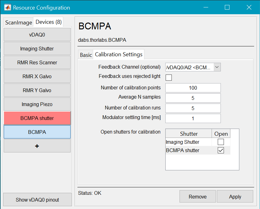
Feedback Channel |
This is the DAQ analog input channel from where a photodiode can be connected to calibrate laser power with the angle of the half-wave plate in degrees |
Feedback uses rejected light |
This is a true (checked) or false (unchecked) parameter that tells ScanImage to interpret the feedback photodiode signal differently depending on whether laser power at the sample is proportional (not using rejected light) or inversely proportional (using rejected light) to the power measured from the photodiode. |
Open shutters for calibration |
The motorized half-wave plate is set downstream of the shutter in the BCM-PA, so the BCM-PA has already been selected to be opened for calibration. |
Once finished configuring the motorized half-wave plate, select Apply. After clicking Apply, the status at the bottom right of the page should say ready. Now you can configure the BCM-PA shutter as you normally would for a digital shutter. Since the shutter is between the laser and the sample rather than between the sample and the PMT, the shutter is already set to be a stimulation shutter.
Once the shutter and motorized half-wave plate device have Ready status, you can pair them with your Imaging Scanner in the ScanImage tab.