Stack Acquisition
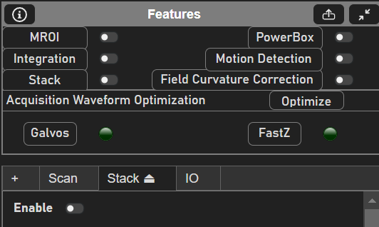
To enable stacks (Volume Imaging), first toggle the stack button in the Features GUI or the Enable button from the Stack Tab. Ensure that a stage is properly configured, along with a fastZ device if desired.
Slice Configuration
|
|
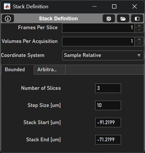
Next, configure the stack slices. There are two ways that a stack can be defined - Bounded and Arbitrary. Each type shares Frames per Slice, Number of Volumes, and a Coordinate System; Frames per Slice and Number of Volumes can also configured from the Main Controls window. The two types of stacks differ by how the slice locations are defined. For example, a bounded stack may start from -25µm to 25µm in Sample Relative Space with steps of 5µm:
Number of Slices |
11 |
Step Size [µm] |
5 |
Stack Start [µm] |
-25 |
Stack End [µm] |
25 |
It is important to understand SI Coordinate Systems so that it is clear how a stack is defined. Briefly, the origin (0, 0, 0) of Reference Space or Reference Coordinates is defined by the center range of the x scanner, y scanner, and the top of the Z actuator’s range. The origin of Sample Relative Space is the coordinate system that applies various transforms to reference space, accounting for factors like a tilted objective or offset stage axes to operate in microns. To work in Sample Relative Space, first complete a stage-scanner alignment.
See below for a description of each stack definition:
Bounded Stacks define the top and bottom bounds of the stack.
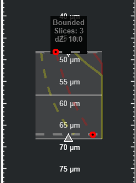
Once the bounds of the stack are defined, the stack can be populated by the number of slices or by the step size. If the number of slices is changed, the step size will change to reflect this, and vice versa if the step size is specified. These properties can be set from the Stack Definition GUI or the ZView within the Viewport.
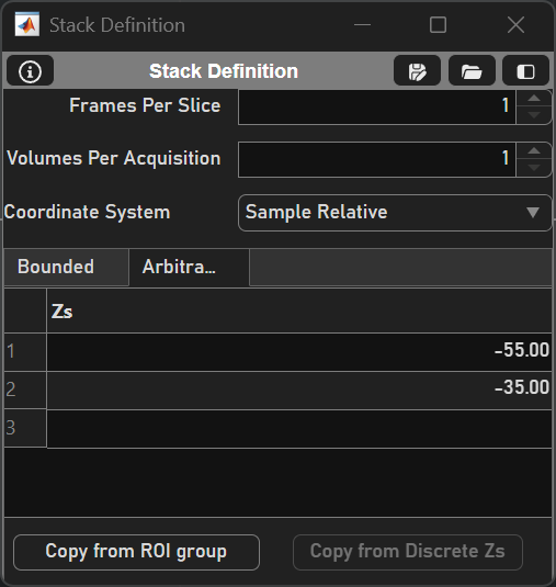
Arbitrary Stacks are configured by entering slice depths into the Zs field. Slices will be acquired in order. Slices can be appended (or inserted in the front of the list) using keyboard shortcuts at the yellow Display Slider. If an ROI group is loaded from the ROI Group Editor, the Copy from ROI group button can be clicked to retrieve all z planes of previously drawn ROIs. If the current actuator is a discrete FastZ device, these Zs can be imported as the slices with the Copy from Discrete Zs button.
Stack Type
ScanImage supports two types of stack:
Slow Stack |
After a slice is acquired, the acquisition stops, the motor moves the focal point to the next slice and the acquisition is restarted. This mode can utilize a motorized stage or a FastZ device. |
Fast Stack |
The motor moves the focal point continuously in Z, while the acquisition keeps running. This mode requires a FastZ actuator that is controlled via an analog command signal. (e.g. Piezo objective positioner, electrically tunable lens, voice coil for remote focusing) |
To learn about the distinction between Slow Stacks and Fast Stacks, visit the Volume Imaging concept page.
Slow Stack
Configure a slow stack by
selecting an actuator (Motor or FastZ)
decide whether the actuator should return to the start (home) position after the stack acquisition is completed
decide whether to lose shutter between slices*
Fast Stack
Configure the fast stack by
selecting a Waveform shape,
indicating whether to Return Home after the stack,
optimizing the fastZ waveform in the Waveform Controls
specifying the volume parameters in the table below:
Waveform |
Waveform shape to drive the FastZ actuator. Options:
|
Return Home |
Return to initial position after the stack acquisition is completed |
Flyback Time (ms) |
Time allocated for flying-back the the Z actuator at the end of the stack Note the flyback time is rounded up to a multiple of the frame duration to determine the number of discarded frames |
# Discard Frames |
(not settable) number of flyback frames, calculated based on flyback time |
Actuator Lag (ms) |
Lead time applied to FastZ drive waveform to compensate for actuator lag |
Volume Rate |
Volume Rate [Hz] |
Test Waveform |
Show the FastZ Tuning Window |
Starting the Acquisition
Clicking the Grab button in the Main Controls window will acquire the stack.
Viewing Images
After a Grab finishes, the stack slices will be visible in the Viewport. Adjust the Display Slider in the ZView to view the desired slice.
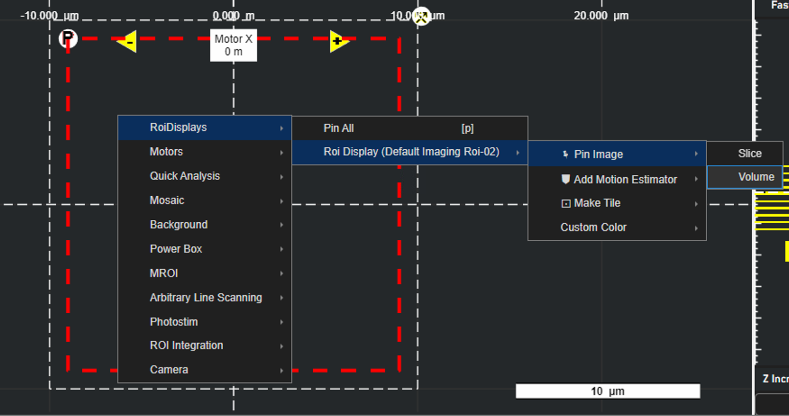
Pinning Images
Acquired images or volumes can be pinned to the Viewport by right-clicking the Viewport and selecting ‘Volume’ or ‘Slice’ under ‘Pin Image’ for a particular Roi Display in the RoiDisplays. To pin all ROIs, select ‘Pin All’ under RoiDisplays (or use the keybind ‘p’). Note that after an image is pinned, the histogram slides cannot be changed.
Power Over Depth
As imaging depth increases, it may be desirable to increase the power of the beam. The Power over Depth Panel enables control of the selected beam’s power between two select depths.