Channels Tab
Feature: Acquisitions
The Channels tab collects the controls for the scan phase, the virtual channel display and logging settings, the per-physical-channel acquisition settings, and the assignment of channels to Z depths. In earlier versions of ScanImage these controls were part of the Display tab; they now live on their own tab in the left panel.
Scan Phase Controls
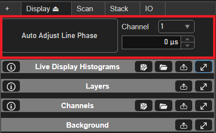
Control |
Description |
|---|---|
Auto Adjust Line Phase |
Automatically detects and corrects the scan phase offset by analysing the channel viewport. |
Channel Selection Dropdown 
|
Selects the display channel for line phase adjustment. |
Manual Line Phase Adjustment 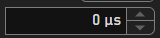
|
Spinner control to optionally manually adjust the scan phase. (See Scan Phase Adjustment). |
Channels
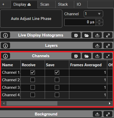
The Channels panel configures the virtual channels that are received, displayed, and logged.
Tip
Double-click a table column header to bulk-set that column for multiple channels from a dialog.
MATLAB syntax may be used in the dialog (e.g. 1:4 to set channels 1 through 4).
Column |
Description |
|---|---|
Name |
The channel name. Defaults to the channel index and may be edited. |
Receive |
Toggles display of image data on the associated channel in the viewport. |
Save |
Toggles whether or not the image data associated with this channel is saved when file logging is enabled. |
τ [s] |
The time constant, in seconds, for exponential smoothing (rolling frame average) of the
channel’s image data. Set to |
Log τ |
Toggles whether the exponential smoothing is also applied to the logged (saved) data. When off, smoothing affects only the live display. |
Physical Channel Settings
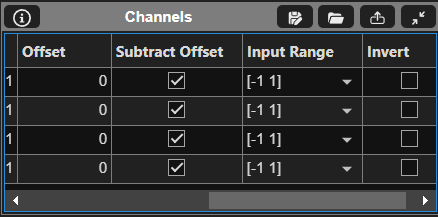
The Physical Channel Settings panel configures the analog acquisition settings for each physical input channel
(e.g. AI0, AI1 …).
Column |
Description |
|---|---|
The physical analog input channel the row applies to (e.g. |
|
Input Range |
A dropdown indicating the voltage range mapping analog values to the digital range on the associated channel. |
Invert |
Toggles whether high digital values indicate black pixels or white pixels. |
Subtract Offset |
Toggles whether or not to apply the value in the Offset field. |
Offset |
Applies an offset to all PMT values for the associated physical channel. (See PMT Calibration) |
Control |
Description |
|---|---|
Measure Offsets |
Measures the channel offsets (dark value) for each physical channel. (See PMT Calibration) |
Auto Measure Offsets |
When enabled, the channel offsets are measured automatically at the start of each acquisition. |
Channel to Z Assignment
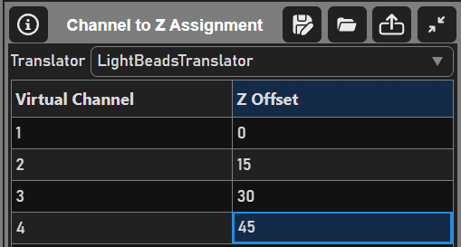
The Channel to Z Assignment panel maps virtual channels to Z depths or fast Z devices using a translator. This is used by multiplexed acquisition modes such as Light Beads, where each virtual channel corresponds to a different depth in the sample.
Control |
Description |
|---|---|
Translator |
Selects the translator that defines how virtual channels are assigned. The table contents change to match the selected translator (e.g. a Z offset per channel, or a fast Z device per channel). |
Assignment Table |
Maps each virtual channel to its Z offset or fast Z device. Double-click a column
header to bulk-set the values from a dialog using MATLAB syntax
(e.g. |
Save | Load |
Saves/Loads the current translator configuration to/from a JSON file using the header buttons. |