Multiple Regions Of Interest Tab
The MROI Tab provides a user interface to plan multiple regions of interest scanning via configuration of ROI Groups, ROIs, and Scanfields.
- Relevant Documentation:
Keyboard Shortcuts
Shortcut |
Description |
|
Activates the tool to add ROIs in the viewport |
|
When an ROI is selected, deletes the ROI |
|
Opens the file explorer to save the current ROI Group |
|
Opens the file explorer to load a saved ROI Group |
|
Toggles whether to draw multiple ROIs when using the Add ROI tool |
|
Toggles whether to draw an array of ROIs when using the Add ROI tool |
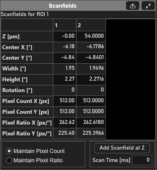
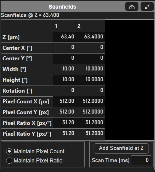
Scanfields Panel
Panel that outlines the properties of the currently selected scanfield and is where scanfields within an ROI are added.
Row |
Description |
Z [µm] |
Depth of the defined scanfield |
Center X [° optical] |
X-component of the position of the centroid of the scanfield. |
Center Y [° optical] |
Y-component of the position of the centroid of the scanfield. |
Width [° optical] |
X-component of the size of the scanfield. |
Height [° optical] |
Y-component of the size of the scanfield. |
Rotation [°] |
Rotation of the scanfield. relative to the imaging scanners Note only imaging scanners using galvos to scan (NI LinScan or vDAQ based imaging set to linear scan mode) can scan scanfields which are rotated relative to their scan axes. |
Pixel Count X [px] |
Number of pixels along the fast axis of the image, in pixels. |
Pixel Count Y [px] |
Number of pixels along the slow axis of the image, in pixels. |
Pixel Ratio X [px/° optical] |
The number of pixels per optical degree of scanning in X. |
Pixel Ratio Y [px/° optical] |
The number of pixels per optical degree of scanning in Y. |
The parameters above are given in a particular coordinate space based on the configuration of the current imaging scanner.
Linear scanners, or those using a galvo as the fast-axis scanner, have their scanfields’ parameters specified relative to the reference coordinate system.
Imaging scanners using a resonant scanner or polygonal scanner as their fast axis scanner have their parameters specified relative to the scanner’s coordinate system.
Elment |
Description |
Maintain Pixel Count / Maintain Pixel Ratio |
Selection determines whether Pixel Count X and/or Pixel Count Y changes when changing the width and/or height of the scanfield. If Maintain Pixel Ratio is selected, then the Pixel Count X and Pixel Count Y scale linearly with changes in width and height. |
Add Scanfield at Z |
Adds a scanfield to the selected ROI(s) at the current Z of the currently selected viewport. |
Scan Time [ms] |
Shows the time taken to acquire the selected scanfield. Note Just the time to acquire the scanfield. The total time for a given frame, which is taken at a slice (or particular depth) of the ROI is given by the sum of the scan times, the sum of the the fly-to times between ROIs, and the frame flyback time. The fly-to and frame flyback times are specified from the XY Gui in the scan tab. If multiple scanfields are selected, then a scan time is not displayed. |
Note
if multiple ROIs are selected, the scanfields of each at the current Z are listed in the table. From there, a row of scanfield properties can be edit simultaneously by selecting multiple cells before editing.
Rois Panel
The ROIs panel allows for creation and configuration of ROIs within the FOV of the imaging scanner.
Table
Column |
Description |
Name |
The name of the ROI. Defaults to “ROI #”, where # refers to the order in which the ROIs were added to the ROI Group. |
Enable |
Whether or not the ROI should be used in the acquisition plan for the next acquisition when the MROI feature is enabled. |
Display |
Whether or not to display the selected ROIs planning graphic. |
Discrete Plane Mode |
Whether or not the planes between defined scanfields for the ROI should be interpolated and used for acquisition planning. If Discrete Plane Mode is enabled and the imaging depth does not coincide with the depth of the scanfield of the ROI, the ROI is not scanned in imaging. |
Add Bidi-Y ROI |
Click the |
Roi Groups Panel
From here, one can change the name the ROI Group used for MROI imaging from the table.