Arbitrary Line Scanning Tab
Feature: Arbitrary Line Scanning
Keyboard Shortcuts
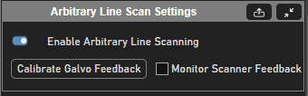
Arbitrary Line Scan Settings Panel
Element |
Description |
Enable Arbitrary Line Scanning |
Sets whether or not arbitrary line scanning will be used in the next acquisition |
Calibrate Galvo Feedback |
Calibrates Galvo feedback assuming that ramping of optical degree target angular position target gives linear ramp actual angular position. Cannot Monitor scanner feedback unless the galvo feedback has been calibrated. |
Monitor Scanner Feedback |
Monitors scanner feedback to display positions throughout a cycle while acquiring and to save to a CSV file if a TIFF is concurrently being acquired. Learn more here Verifying the Scan Path |
Element |
Description |
Arbitrary Line Scan Rois Panel
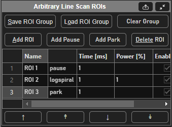
Table Column |
Description |
name |
Name of the ROI |
Stimulus function of the ROI |
|
Time [ms] |
Duration of the stimulus function in milliseconds |
Power [%] |
Power that the beam modulator paired with the stim scanner will be set to while executing this stim function Note This will override what is set from the beams slider in the |
Enable |
Whether or not the given ROI will be used to determine the scan path in the next acquisition |
Display |
Whether or not the ROIs data will be displayed in the viewport when acquiring. |
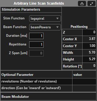
Arbitrary Line Scan Scanfields Panel
Element |
Description |
Stim Function |
Decides the path that the X, Y, and optionally fastZ scanners will trace for the selected ROI |
Beam Function |
Decides the variation of the power thoughout the execution of the selected ROI |
Duration [ms] |
Duration of the stim function |
Repetitions |
The number of times that the selected stim function should be repeated before moving to the next stim ROI in the ROI group Note If the stim ROI does not end where it starts, then the actuators will need to perform a step to get from end to start which can affect the scanners’ ability to trace exactly what was drawn. |
Z Span [µm] |
The size of the ROI in the z dimension for particular Stim functions that make use of it. At the time of writing, such stim functions making use of this are: - zcoil - zspiral |
Positioning parameters are pulled into a table:
Element |
Description |
Z |
Decides the path that the X, Y, and optionally fastZ scanners will trace for the selected ROI |
Center X |
Decides the variation of the power thoughout the execution of the selected ROI |
Center Y |
Duration of the stim function |
Width |
The number of times that the selected stim function should be repeated before moving to the next stim ROI in the ROI group |
Height |
The size of the ROI in the z dimension for particular Stim functions that make use of it. At the time of writing, such stim functions making use of this are: - zcoil - zspiral |
Rotation [°] |
Rotation of the selected ROI |
Each stimulus function comes with its own optional parameters. These are listed in another table.
Beam modulator
Column |
Description |
Beam Modulator |
[Non-Editable, set from resource configuration] Beam modulator device that has been paired with the imaging scanner. |
Power |
Power of the selected stim ROI |
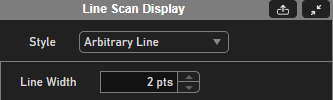
Line Scan Display Panel
Element |
Description |
Style |
Selects the style in which arbitrary line scan data should be displayed |
Arbitrary Line Display Style
This is the default display style. The fluorescence data is depicted over the parts of the path where it was collected.
There is one option for altering the display style here:
Line Width: sets the line width for the path which can help make the image formation more coherent.